
 SHIPS TODAY
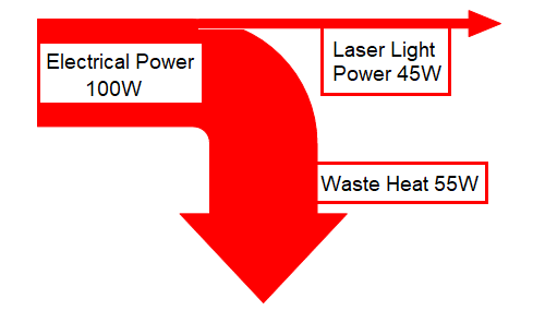
When operating a laser diode, proper thermal management is critical to avoid damage. A few key aspects to consider are the generation and dissipation of waste heat, laser diode operating temperature, and proper heatsinking. This article will focus on TO-Can packages, giving consideration to these key aspects and providing useful information for proper thermal management.
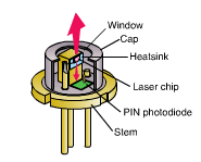 The Transistor Outline package (or TO-Can) was developed to create a highly reliable (often hermetically sealed) package with a very low thermal resistance (impedance), standardized to keep costs down and for universal integration in accordance with JEDEC (Joint Electron Device Engineering Council). A TO-Can consists of a TO header and a TO cap. The header, typically made of copper for its low thermal resistance, contains internal components such as a laser diode chip or die, a photodiode, and a thermoelectric cooler (TEC). The cap, typically formed from steel, encloses these internal components, providing a barrier for contaminants such as moisture and dust, and holds any optical elements in place such as a window or focusing optics.
Waste Heat – Many customers do not appreciate the importance or the complexity of removing waste heat. Heat is the most significant cause of field failures, especially for higher power laser diodes. You must remove waste heat efficiently and instantaneously or the laser will be catastrophically damaged or, at a minimum, experience a shortened lifetime. One of our previous blogs, titled “Understanding Laser Diode Lifetime,” will provide further reading on some critical aspects that affect the lifetime of a laser diode, including die mounting, facet damage, and drive current.
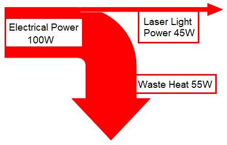 You must ensure the laser diode has an adequate heatsink for the waste heat produced. Depending on the semiconductor laser type and wavelength, laser diodes are typically 10 – 60% efficient at converting electricity into optical output power (laser light). The remaining energy not converted into light is converted into waste heat. A simple method for determining the amount of waste heat is to take the total input power (Amps*Voltage=Input Power Watts) minus the optical output power (Watts). The balance is the amount of max waste heat in Watts. The laser diode die will always run hotter than the surrounding components, package, and the heatsink. With all the generated heat confined to a small area within the package, ensuring a solid and secure connection to an adequate heatsink is critical for transferring this heat.
Effectively transferring heat between two surfaces, in this case between the base of the TO-Can package and the mounting surface of a heatsink, typically comes down to two main factors. These two factors are the thermal conductance of the package and heatsink materials and the thermal resistance (impedance) of the interface between the two. The higher the impedance, the lower the rate of heat transfer. Minor, even microscopic imperfections in the surfaces of the two components create tiny gaps when joining these surfaces together. Suppose these gaps are filled by an insufficient material such as air, with low thermal conductivity. In that case, the interface will exhibit a high thermal resistance, impeding the efficient transfer of heat from the package to the heatsink. There are some primary considerations when attempting to minimize the interface’s thermal resistance:
- How efficiently the materials conduct heat.
- How minimizing surface imperfections or introducing compression force can reduce gap size.
- How thermally conductive the material is, used to fill any remaining gaps.
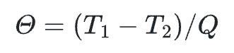
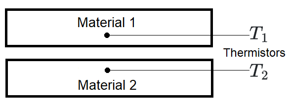
The following equation is useful for calculating the thermal resistance or impedance between two materials using two temperature sensors (thermistors):
|
T = Temperature (oC) |
|
Operating Temperature – Most lasers have a recommended operating temperature and a location where this temperature is measured. Suppose you run a laser diode at a temperature higher than recommended. In that case, the lifetime of the laser will reduce exponentially as the operating temperature increases above the recommended temperature, perhaps to the point of catastrophic failure. Diode laser degradation accelerates with increased temperature. Operating at a temperature lower than recommended for many laser diodes can slightly increase the output power (higher efficiency), improve lifetime, or both. Therefore, one should minimize the operating temperature when feasible. However, lowering the diode laser temperature below 15 °C is only suitable in a hermetically sealed housing with a dry inert atmosphere (e.g., Nitrogen), as condensation will irreversibly damage laser diodes. For example, GaN (gallium nitride) and AlGaN (aluminum gallium nitride) laser diode facets will immediately oxidize when exposed to oxygen.
 Heatsinks – Most all laser diode packages will need some form of heatsinking. The heatsink must be capable of dissipating the waste heat generated by the laser. Lower power devices may only need to be mounted to a baseplate. However, higher power devices require a more substantial heatsink or a forced air, finned heatsink, and laser diodes arrays (bars) may need active cooling to handle the waste heat. Furthermore, suppose the specific laser diode die is not temperature sensitive. In that case, you can consider a smaller package size and a simple heatsink, as that die can operate with negligible wavelength and power fluctuations due to changing temperatures. However, if the die is temperature-sensitive, then a more substantial heatsink, and perhaps a larger package, would be necessary to maintain a constant temperature and avoid fluctuations in performance. There is more surface area to transfer heat more efficiently with larger package sizes.
The best heatsink material is copper, but aluminum is also a suitable heat conductor. The surface should not be anodized in the region where the laser package contacts the heatsink if aluminum is used. The aluminum oxide anodized coating makes an effective thermal insulator which is detrimental for heat transfer. The heatsink surface should be machined flat and smooth where it will contact the mounting surface of the laser package to allow for efficient heat transfer. The heatsink surface should be finely milled or lapped (flatness: 0.5 μm, roughness: 0.5 μm), clean, and free of scratches to guarantee good thermal contact. High-quality, void-free bonding of the package to the heatsink lowers the overall impedance for efficient heat dissipation. For further reading on mounting and heatsinking pitfalls, check out our article, titled “The Three Most Common Mistakes When Mounting and Heatsinking a TO-Can.”
 The heatsink may be cooled by air, water, or a thermoelectric cooler (TEC). Depending on the type of laser, an air-cooled heatsink may provide sufficient cooling. An air-cooled heatsink can maintain an operating temperature a few degrees above your ambient temperature if sized correctly. However, if the ambient temperature changes, the heatsink temperature will also change. This temperature change will not provide stability of the laser wavelength and output power. Most often, active cooling of the heatsink is necessary. Actively cooled heatsinks offer much better heatsinking performance and introduce temperature control into the system. Active cooling usually is either water-cooling or thermoelectric coolers. The most straightforward design of an actively cooled heatsink is a metal plate with a cooling hole that allows coolant to flow through the heatsink. Typically, the coolant liquid is water for ecological reasons and because of its high heat capacity.
 Thermal Spacer – In permanent installations, using a silver-filled epoxy at the interface can improve the heatsinking effectiveness. However, if using silver-filled epoxy, ensure that it is a “space-qualified,” low outgassing type to avoid contamination of the laser facets (Epoxy Technology H21D, for example). An indium foil spacer can be used to reduce the thermal impedance of the laser package to the heatsink interface. However, in our experience, indium foil offers a negligible improvement over a good copper-to-copper interface.
Temperature Drop Check – When testing out a heatsink configuration, it is wise to test the temperature drop between the laser package and the heatsink using a very small thermocouple touched to the base of the laser package. The temperature drop during laser operation should be only 1-2° C.
Wavelength Check – Another test for the heatsink configuration is to check the laser emission wavelength at the specified current and operating temperature. A much longer wavelength than specified on the datasheet supplied with the laser indicates bad thermal contact and thermal overload of the diode laser. Therefore, you must improve the thermal contact before continuing laser operation. The laser emission wavelength will change with operating temperature: the wavelength increases approximately 1nm for every 4° C temperature increase (~0.25nm/K). This value varies by wavelength.
Talk to a knowledgeable Product Manager today by emailing us at [email protected] or by clicking the button below!
Have questions?
Check out our Knowledge Center
See our Lasers 101 page and our Blog and Whitepaper collection for even more in-depth reading!