
 SHIPS TODAY
Introduction
Machine vision is defined as the substitution of the human visual senses and decision-making ability, by image acquisition and computer analysis to perform an inspection task. This process is most commonly utilized as an active imaging technology to automate inspection and analysis for process control and robot guidance in industrial applications. As automation has become more and more prevalent in the manufacturing sector, machine vision technology has rapidly grown into one of the largest markets for laser diodes around the world. Just as with all automation technology, although it started in the factory setting, machine vision has rapidly been making its way into field-deployable technologies as well. Last fall, we wrote a blog post exploring one such field deployable application, laser rail inspection. In this application note, we are going to take a deeper dive into the subject by first reviewing the technology as a whole and then reviewing its use in rail inspection and roadway inspection.
Machine Visions Lasers Sources
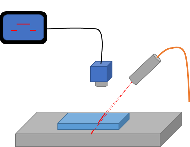
When compared to traditional light sources, lasers provide a much higher contrast with the background image providing the computer algorithm with a more precise reference source. As a result, lasers have been widely deployed as structured lighting in many image processing systems. Machine vision lasers are typically beam shaped into lines, dots, and other geometric patterns (such as crosses, circles, and grids) and they can come in a wide variety of wavelengths and powers depending on the systems requirements. Each of these geometries has its own unique advantages, but lines tend to be the most commonly used laser shape in modern machine vision technology. Lines are the most popular because if the laser is offset at an angle from the camera, a 3-dimensional image of the object can be reconstructed through a process known as triangulation. As demonstrated in the figure below, when an object passes under the laser line, there is a resultant spatial offset between the laser light on the top of the object and the light on the sides. By measuring this offset in the image, also shown in the figure below, an algorithm can then calculate the height of the object based on the known angular offset. While the example below shows a rather simple example, this same process can be applied to highly complex objects as we will discuss below.
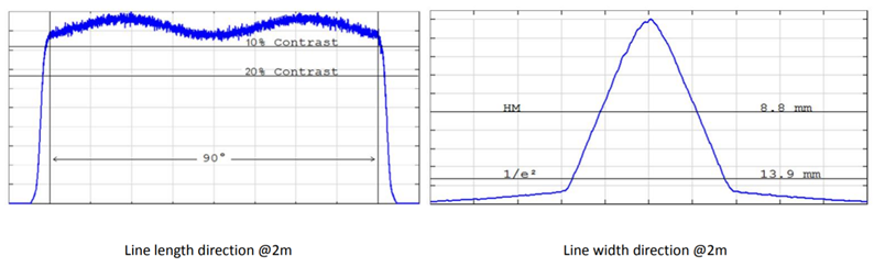
In the previous blog post on this subject, we discussed that when machine vision is used for the inspection of small parts, laser lines and other shapes are typically achieved through the use of diffractive optical elements, which when used with single mode diode lasers can create a wide variety of geometric shapes and patterns. While these low power single mode lasers are typically sufficient for inspection of small parts on a production line, as the size requirements on the line continue to increase the use of multimode high-power lasers becomes a necessity. As a result, the higher power density becomes an issue for diffractive optics to handle as they are unable to shape multi-spatial mode lasers. As a result, to generate long lines from higher powered multi-mode laser diodes either galvanometric scanning mirrors or micro-optic arrays are required. While scanning mirrors can be somewhat effective at producing uniform laser lines, they suffer from reliability issues, especially in rugged environments, making them a less than ideal solution for deployable field systems. Micro-lens arrays, on the contrary, are a monolithic solution which can either be placed at the output of a fiber-optic cable or directly in front of the diode bar to exploit inherent astigmatism and produce flat top laser lines. In the previous blog, we showed the example of one such flat top laser source, the FocusFlux from Focuslight. It can create a high-power laser line at distances up to 3 meters from the source with fan angles as large as 110-degrees, making them ideal for inspecting larger objects and surfaces. In the figures below, you can see an example of the laser line cross-sections for a FocusFlux EL series line laser system from Focuslight, measured at a distance of 2 meters from the source.
High Power Machine Vision Applications
In our previous blog post on the subject, we explored how these laser sources are used for rail inspection and how this enabled a machine vision system to detect defects as well as to measure diameters, edges, and gaps. Line-shaped high-power lasers have enabled these automated systems to subsequently measure and align all the features of a railway, including the spatially contorted and oddly shaped objects. Additionally, high-power lasers are now being used in machine vision systems for road inspection where instead of measuring raised surfaces as in the previous example, they measure cracks and potholes in the road. By utilizing high powered fiber coupled laser diodes, they are not only able to generate long lines, but these lines can have sufficient power density to allow for fast camera integration. By reducing the integration time and pixel pitch of the camera in use, modern road inspection systems are capable of imaging a wide variety of surfaces including asphalt, chipseal, porous pavement, and both tined and untined concrete at incredibly high speeds. One system on the market from Pavemetrics, the LCMS-2, is capable of providing images up with 1 mm resolution at speeds over 60 miles per hour.
Systems like the one made by Pavemetrics are rapidly becoming an indispensable tool for road inspectors, particularly when it comes to determining structural integrity. One example of a high-powered laser system which can facilitate these systems is the BWT line of 976nm high-power multimode fiber coupled laser diodes. The K976F line of lasers is available as compact fiber-coupled OEM packages, ideal for integration into field portable machine vision inspection systems. These lasers are available with output powers ranging from 4 watts to 200 watts, all featuring a low threshold current, high slope efficiency, and high reliability.
Final Thoughts
Now that you have an understanding how lasers are used to improve contrast and triangulate the size and shape of 3-dimensional objects, it should be easy to see why this technology is rapidly migrating from the production line to the field. As more and more field applications are discovered the need for high power fiber-coupled diode lasers as machine vision sources will continue to grow. Here at RPMC Lasers, we provide the most comprehensive array of fiber-coupled diode lasers on the market with powers into the kilowatts. RPMC Lasers is proud to be the exclusive North American distributor for BWT Beijing, the leader in high power fiber-coupled diode lasers. BWT offers both volume Bragg grating stabilized and Fabry-Perot diodes, specializing in the development and manufacturing of high-performance diode laser components and subsystems. As a leading supplier of fiber coupled diode lasers, BWT Beijing provides lasers in a wide range of wavelengths (blue through infrared) and output powers (milliwatts through kilowatts). Those capabilities, coupled with a team of skilled and experienced specialists in high power diode lasers packaging, beam shaping, and fiber coupling, make them an ideal choice for machine vision solutions.
For detailed technical specifications on our high power fiber-coupled diode lasers click here or talk to one of our laser experts today by calling 1-636-272-7227.