
 SHIPS TODAY
Laser alignment can be a challenging task, but aligning a laser beam doesn’t have to be as complicated as it might seem with the right optical alignment tools and proper laser alignment techniques. Multiple optical alignment techniques have been developed over the years, utilized by technicians and engineers to simplify the alignment process. With the development of these universal laser beam alignment methods, along with some laser alignment tips and tricks, you don’t need to be a laser expert to perform your alignments with relative ease, ensuring your laser beam path is right where you want it to be and your beam is on target every time. This will not be a comprehensive, step by step laser alignment tutorial for every situation. However this blog will cover a few of these tips and methods, focusing on the benefits of utilizing time-tested, high-quality HeNe lasers to assist in the alignment process. If you are looking for a very in-depth optical alignment tutorial, or have a particularly unique or complicated laser alignment challenge, you may consider looking into a more focused laser alignment training service.
What is a HeNe?
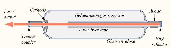
A helium-neon (HeNe) laser is a continuously operating or continuous-wave (CW) gas laser. The gain medium is a 10:1 mixture of helium and neon, pressurized within a glass tube. When applying a direct current (DC) to two electrodes on opposite ends of the tube, helium atoms are excited into metastable states. When excited, helium atoms can efficiently transfer energy to neon atoms with quite similar excitation energies. Due to the multiple energy levels of neon atoms, numerous laser transitions are possible with this type of gas laser. The most common transition used today is 632.8nm (red). However, 543.5nm (green), 594nm (yellow), 612nm (orange), and 3.39µm (MWIR region) are also possible by utilizing resonator mirrors with coatings with peak reflectance at these specific wavelengths. If you’re interested in reading a bit more about the history and development of the HeNe laser, check out our recent article titled “HeNe Lasers: Bright Past, Brighter Future.”
Visible Laser Light for Alignment
 Are you wondering how to align an infrared beam? Aligning an infrared wavelength laser can be tedious and frustrating since you’re dealing with an invisible beam. Therefore, the use of visible laser wavelengths in the red or green regimes proves to be quite helpful for actively visualizing your optical path during the alignment process. In the case of red wavelengths, the human eye’s sensitivity starts to drop quickly as the wavelength increases toward the infrared. So, choosing a shorter red wavelength (e.g., 630nm vs. 690nm) provides a much higher level of visibility, especially with high levels of ambient light. Some optical components may cause alignment issues when using specific wavelengths due to various wavelength-dependent dielectric coatings on optical lenses and other chromatic aberrations. Typically, these issues are only seen in optical lenses and not on reflecting mirrors. So, if your system involves optical lenses, be sure to note any conflicts with your lens coatings or substrate composition and the visible wavelengths you might use to align the optical system.
A Quick Note on Laser Safety
Make sure to always practice proper laser safety. Ensure that no one can walk into your beam path, you have any necessary warnings posted, and that you have the properly rated laser safety goggles for any wavelengths involved in both the initial alignment process and for your application or experiment.
Laser Source Alignment Tips and Considerations
Collimation, Divergence, and Pointing Stability
When attempting an alignment, your laser beam must be collimated so that the beam diameter remains at least approximately unchanged over the entire length of the beam path. Beam divergence can make things trickier as the beam diameter increases over distance, reducing your alignment accuracy. Another critical property to consider is pointing stability (angular drift). Fluctuations in pointing stability, leading to the angular displacement of the beam, can have detrimental effects on your alignment process as the beam moves position over time due to thermal expansion or mechanical shock. With the proper tube material composition and a high level of mechanical symmetry, manufacturers can minimize the effects of thermal expansion. High-quality HeNe lasers can achieve excellent pointing stability on the order of 3mm of angular drift over a distance of 100m (e.g., pointing stability of 0.03 mrad).
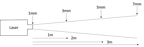 Diagram example illustrating how rapidly an uncollimated laser beam can diverge
Equipment and Setup
Sound mechanical design of your optical alignment equipment and setup can help minimize the effects of mechanical shock, helping to maintain pointing stability. For example, a HeNe laser module’s rigid, cylindrical body is perfect for stable, repeatable mounting in a V-block/optical post mount assembly, mounted to a laser alignment optical table (breadboard) in your work area. You can even create an alignment jig on the breadboard, utilizing the two pinhole method, for repeatable reference for your various alignments. This easy laser alignment procedure involves similar steps described below in this article (‘Parallel Z-Fold Configuration’). The difference is that you set up two small apertures, set to the same positions in the X- and Y-axes at some distance from each other, and you adjust the angle of your two mirror mounts to steer the beam directly through the two apertures. The two apertures replace an optical alignment target reticle or card with an ‘X’ / ‘+’ drawn on it to ensure your beam will be aligned orthogonally and parallel to the table.
Beam Offset / Beam Displacement Optics
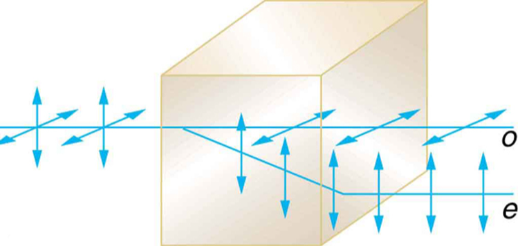
Specific considerations are necessary when utilizing specialized optics, such as a polarizing beam displacer. These optics separate an unpolarized beam into two orthogonally polarized output beams parallel to each other. Suppose this optic is to be inserted after general system alignment. In that case, you need to be aware of the displacement or offset distance of the extraordinary polarized beam (ordinary polarized beam transmits straight through the optic). If the optic is present during alignment, consider whether the component is designed for use within a narrow wavelength region or broadband use (i.e., working throughout a much larger wavelength region). Your alignment wavelength and the polarizing optic may not work together, hindering your alignment measurements and efforts.
Optical Alignment Configurations
Parallel Z-Fold Configuration
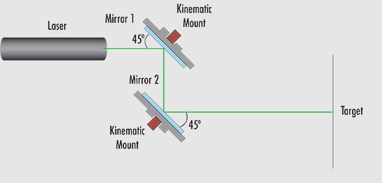 There are a couple of alignment methods to choose from, utilized for alignment areas with tight space constraints, or perhaps chosen based on the position of the laser head or on where the beam exits. Firstly, there’s the ‘Parallel Z-Fold Configuration.’ This configuration involves two optical alignment mirrors on tip-tilt (kinematic) mounts, allowing for simple, precise adjustments for angular displacement and position and ensures the beam is incident upon the two mirrors at approximately the same angle. For simplification, it is advised to mount each mirror at ≈ 45o, relative to the beam propagation axis to redirect the beam 90 degrees. Adjust the screws of Mirror 1 to ensure proper beam positioning in the X- and Y-axes (horizontal and vertical) incident upon Mirror 2. Once you have the first mirror aligned so the beam hits the second mirror, Mirror 2 is then adjusted to correct the beam’s angular displacement and align the beam to the end target.
Simplify With Reference Points
Utilizing two different reference points – one on the surface of Mirror 2 and the other being your end target – minimizes the number of adjustments required to attain proper alignment. A basic cross-hair reticle (or even a piece of card stock/business card with an ‘X’ or ‘+’) is very effective during this process to check the alignment. Suppose the desired alignment is parallel to the table (or incident normal/perpendicular to the target). In that case, both reference points at Mirror 2 and the target should be in the same position in the X- and Y-axes. Utilizing fixed position mounts with pins allows for quick and repeatable placement and removal of your crosshair reticle, ensuring you can always replace it to the original position. This Z-Fold configuration is often a good option when aligning more than one beam to the same target. However, when attempting to combine multiple beams with different wavelengths, you may need to replace the mirrors with appropriate dichroic filters, matching the wavelengths involved.
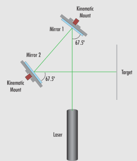
Figure-4 Configuration
The following setup – the ‘Figure-4 Configuration’ – is identical to the Z-Fold format in terms of the specific process. This Figure-4 setup is a bit more complex. Still, it allows you to perform your alignment in a smaller footprint, and your final aligned beam will be perpendicular to the direction of propagation from your laser source. You will still use two kinematic mirror mounts, two targets (one at Mirror 2 and one at the end of the beam path), and you will adjust Mirror 1 for ‘X’ and ‘Y’ positioning and Mirror 2 for angular displacement and aligning to your end target. The physical difference in the setup allows for the Figure-4 shape and perpendicular beam by placing your two mirrors – mounted at 67.5o angles – as you can see in the diagram.
In Conclusion
The basic concepts here are the same, and you could even significantly change the positions, angles, and distance between components to fit your specific needs and layout better. No matter which of the above configurations you choose, following this alignment method should allow you to minimize your efforts and efficiently align most standard laser setups. Remember, with the right tools and proper techniques, aligning a laser beam doesn’t have to be as complicated as it might seem.
High-Quality HeNe Lasers vs Laser Diodes for Alignment
There have been many discussions around whether or not diodes will replace HeNe lasers. However, while this may be more plausible for certain applications as time goes by, especially in industrial environments for long life time and robustness are key, the superior beam quality and competitive cost of HeNe lasers ensures a solid foothold in applications where excellent beam quality is critical. Beam quality is not essential for alignment per se. However, certain aspects of the beam quality will affect your alignment, such as divergence, which we discussed earlier. The mode of a typical laser diode is inherently elliptical, astigmatic, and highly divergent. These beam characteristics mean that the output from a laser diode would need some corrective optics to shape the beam to the point that it is usable for alignment. Alternatively, the output from a typical HeNe laser is fundamentally Gaussian, circular, and with minor divergence. Therefore, the HeNe laser is ready for alignment purposes, as is in its base form.
See Our Selection of HeNe Lasers!
How Can We Help?
One of our trusted partners, LASOS, designs, develops and manufactures high quality HeNe and Ar-Ion laser systems, and they have been in the game since shortly after the inception of the laser industry. Since then, LASOS has been perfecting the process of manufacturing long life, low noise, and high stability HeNe laser tubes and modules with excellent beam quality.
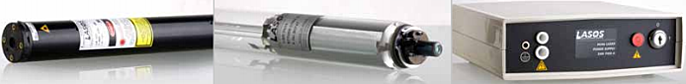
The HeNe lasers from LASOS boast an excellent TEM00 beam, robust mechanical design, a long service life of up to 30,000 hours, and are available in 543nm, 594nm, and 632.8nm wavelengths, with output powers from 0.5mW to 20mW. Choose between standard and customized models, with available options such as single-mode or multimode, random or linear polarization, Brewster window tubes, and fiber coupling. All models can be provided with either a laboratory power supply, or one of three OEM power supply versions. Designed for long life, low noise, and high-stability, with many customization options, these HeNe lasers are perfect for applications including spectroscopy, interferometry, holography, medical, laser system alignment, and more!
Talk to a knowledgeable Product Manager today by Contacting Us here, or by calling us at 636.272.7227!

|
LASOS, an ISO certified company, designs, develops and manufactures high quality HeNe and Ar-Ion laser systems with a special focus on OEM applications in the Biophotonics, Microscopy, Raman Spectroscopy and Holography markets. With company roots and laser manufacturing dating back to 1966, LASOS brings many years of experience and expertise to the design and manufacturing of sophisticated laser systems. With the many years of experience and customer’s success, LASOS has positioned themselves as a reliable partner and supplier to the world-wide, laser electo-optics community. |
|